Having recently setup control of a light at home over the internet using a wired solution as detailed in my previous blog post, I started to investigate options for a wireless alternative; as running cables, although the most reliable option, is not always practical. Most of the commercial wireless IoT devices operate on either the 2.4GHz frequency band or in the ranges 863-876 MHz and 902-928 MHz. In 2014 Ofcom designated specific IoT frequency bands as 870-876 MHz and 915-921 MHz.
Wireless standards & frequencies
The most common standards used by IoT devices are 802.11 Wifi, (usually supporting only 2.4GHz 802.11b/g/n standard), Z-Wave, ZigBee XBee, Bluetooth Low Energy (BLE), and LoRa. On the 2.4GHz band there is Wifi, ZigBee, XBee and BLE, sitting in the 863-786MHz and 902-928MHz bands we have Z-Wave, LoRa and also some XBee and ZigBee devices.
The cheapest and most common wireless devices which you can buy for use at home use the 433MHz band, this includes devices such as wireless door bells, thermometers, mains socket switches and garage door controllers. These have been around for a long time well before "IoT" was even a thing, the main reason for the popularity of 433MHz is that it is a license free frequency band in all European countries, the equivalent for the US and Asia is 315MHz. Although 2.4GHz is a worldwide licence free band, and the other bands are license free in different countries, the protocols used are more complex, increasing the cost of the devices.
A 433MHz signal penetrates walls and other obstacles better then 2.4GHz, so should give better range for the same output power in a house, the downside is that most of the devices use simple ASK/OOK modulation which is more susceptible to interference. Devices which use 433MHz also do not use any kind of authentication or error detection/correction, devices are controlled by the transmission of simple pulse patterns and the communication is 1-way so there is no way to know if the state of the receiving device has changed. Most of the commercial devices used fixed patterns based on some kind of encoding strategy such as "Manchester" encoding.
By replicating the function of the controller/transmitter, we effectively can turn cheap wireless mains socket switches or other similar devices into "IoT" devices.
433MHz hacking
I was already aware that it is possible to control a 433MHz device by simply capturing the pulse train sent by the controller/transmitter and replaying it, so with this in mind I purchased a set of "Energie" remote controlled plug socket adapters. The kit comes with 4 socket adapters and a little remote control fob for switching each socket on and off. There is a little controller board available for the Raspberry Pi that allows control of the sockets from Python, but I was looking for a solution that could work for any 433MHz device using an Arduino. A microcontroller (MCU) such as the ATmega328p used on the "Arduino Uno" board is much more suited to generating signals as opposed to a Raspberry Pi running an OS, which cannot operate in real-time.
I discovered a project called RFLINK, it only runs on an Arduino Mega as it requires the extra Flash storage and SRAM of the ATmega2560 MCU. RFLINK is capable of decoding and replaying signals captured using cheap 433MHz receiver and transmitter modules of the kind you can buy on Ebay for a pound or so. While shopping for those parts I also picked up a cheap generic remote control fob with 4 buttons on it for testing purposes.
I tried RFLINK with an RXB6 receiver and an XD-FST FS1000A transmitter using the wiring suggested in their documentation. I tried various 433MHz devices that I had lying around including the Energie sockets and found that RFLINK was able to capture and replay some of the control signals, however some devices could not be decoded. Enabling debug mode in the RFLINK config showed a description of the pulses, but if RFLINK couldn't detect and decode the pulse encoding scheme, there is no way to replay the signal, rendering it only usable for some devices.
I had also bought an Energy Egg (discontinued) remote control plug socket adapter and light switch very cheap from Maplin for testing. The controller is a little egg shaped unit containing a PIR sensor with button on top, it is designed to sense when you enter and leave the room. Unfortunately, even though RFLINK was able to decode the signal, replaying it did not work, for some reason the socket just would not switch.
DIY RF Controller
I decided the best solution was to write my own code to capture and replay the signals. All the Arduino needed to do was capture and record the pulse train sent by the transmitter and replay it when required, there is no need to try to decode the pulses into a numeric value or string. My plan was to allow control commands to be sent using serial communication over the Arduino's USB port, the Arduino would be connected to a Raspberry Pi running a web API acting as a HTTP to USB Serial bridge. Yes there are ways to add wired and wireless networking to the Arduino, but I decided that it would be better to use the power of the Raspberry Pi for that and leave the Arduino to do just the precise signal timing work with a simple communication interface.
The Hardware
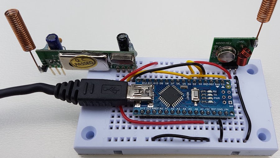 An Arduino Nano was used due to its small form factor, the circuit was the same as used with the Mega and RFLINK but with the following changes:
- RXB6 receiver pin 7 (data) -> Arduino Nano pins 3 and 4
- FS1000A pin 3 (data) -> Arduino Nano pin 4
- FS1000A pin 2 (vcc) -> Arduino Nano vcc pin
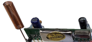
I soldered the 3 capacitors to the receiver module along with a small helical antenna (from Ebay) to both modules. I stretched out a spare antenna to find out that it was 32cm long, close enough to 433MHz half wavelength of 34.5cm. I assembled it on a breadboard for testing before soldering it up on some veroboard.
The Software
It has been a while since I last wrote any code for a microcontroller, about 7 years ago I started to write some code for a vehicle dashboard display project to show engine data. For that I used a KS0108 128x64 LCD display wired to a Teensy MCU board and the Arduino IDE for writing the code, but it ended up being a project that I didn't have time to finish. A long time before that, for my final year university project I made a vehicle Engine Management system using an 8051 MCU with all the components required to read sensors and control ignition and fuelling. For that I wrote the software for the 8051 in assembly language and the Windows software for calibration using Visual Basic. It worked well and ran my car for many years, but since then I have only needed to work with higher level languages.
Arduino's are programmed in C/C++, an Arduino "sketch" looks a bit different from a traditional C program, but behind the scenes it is modified before being passed to the AVR GCC compiler. The Arduino IDE doesn't seem to have progressed much since I last used it, but I discovered that my current favourite IDE, VS Code has an extension available for Arduino and C/C++. You still need the Arduino IDE as that's what the extension uses to compile and upload the code.
After deciding on a basic structure for the code, and being used to thinking and developing in an OOP fashion, I decided that the code should be written using C++. I also wanted to take advantage of the Standard Template Library (STL), so I had to find a suitable STL implementation for AVR. The code is available in my GitHub Repository along with usage instructions.
Security
The security of the 433MHz devices that I have used is virtually non existent, there is only the element of proximity to prevent someone else from controlling your devices. Due to the short range of the signals and likelihood of someone with technical skills and equipment standing outside to sniff the signals and gain control of a few lamps connected to wireless plug socket switches, it's not really a huge issue. I would certainly not use these unsecured 433MHz devices for any physical safety or security related functions such as heating, alarm control or security sensors etc. The main issue with any wireless device, secured or otherwise, is signal jamming rendering them useless.
Conclusion
Using some very cheap parts it possible to build a controller to turn low cost 433MHz wireless devices into IoT devices. As long as you understand the potential security risks, it provides a low cost alternative to off the shelf IoT devices that use more complex protocols such as Z-Wave or ZigBee. Even those protocols, like most other things are not completely secure. Encryption in Z-Wave is optional so you won't know if your Z-Wave IoT device is actually communicating over an encrypted connection. ZigBee is an open standard based on the IEEE 802.15.4 personal area network (PAN) radio standard and encryption is part of the protocol. As secure as they claim to be, both of those protocols have already been exploited.